Sprung zum Abschnitt


Sie können die gesuchte Antwort nicht finden? Keine Sorge, wir sind hier, um zu helfen!
Kontakt zum SupportHow to create hsbRoofElement-hsbFloorElement panels
The function of this document is to instruct the users of hsbcad on how to use the hsbElement menu to create Roof and Floor Panels.
An hsbPlane is a horizontal/sloped surface that can be used to project hsb entities to (walls) or used to create hsb entities on the plane (floors, roofs).
What are the steps to create Roof-floor panels
To create floorpanels you need to.
1. Define a Roof or Floor Plane area.
2. Divide Element.
3. Assign Roof or Floor Element Parameters.
4. Modifying Elements.
5. Modifying Element Parameters.
You do have an option to skip defining the floorpanel area and instead go straight to option ‘Divide Element’.
How to Define a Floor Panel Area

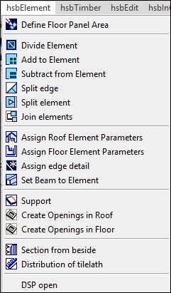
Use the command hsbElement\Define Floor Panel Area.
This is the exact same command as creatingroof planes. Instead of giving them a slope you create a horizontal plane.
However, it isworth noting that there is a difference in how you use this function inrelation to working with Floor Elements and Roof Elements.
In the case ofFloor Elements, you use this function to define your Joist Span direction, andas such you can have more than one Floor Area to define considering that on anyfloor level, you can have Joists running front to back or left to right.
In the case ofRoof Elements, this function is used in the manual definition of a Roof Planeand as such there is normally only one Roof Plane used for each slope on theroof. However, it is worth noting that this function is only used in caseswhere the hsbPlane commands cannot solve a very complex roof shape and manualintervention is needed.
Here youhave the options to select your defining points, make a simple rectangle orconvert a closed polyline.
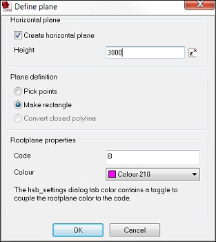
- Height - There are Different ways of setting the floors heights. In this case you will specify a height in this window. Keep in mind that when you create your floor system in a project you will need to know the top or bottom height of the floor so that it generates at the correct elevation.
- Pick Points - The pick point’s option can beused where you want to define the floor panel areas by selecting object snappoints on the base plan or on the hsb walls.
- Make Rectangle - Use the Make Rectangle option ifyou want to create panels that are rectangular or if you want to create a floorplane by drawing/converting a closed polyline.
- Convert Closed Polyline - Use the third option if you wantto create a floor plane by converting a closed polyline to a floor plane. Youonly need to use this option if the polyline is sloped in the z plane. If youuse this option you will need to switch off create horizontal plane option.
Note: What we are basically doing here is defining a plane object. Please note that this item is not an element and as such cannot be used as one. Please remember that the Area/Plane does not automatically get attached to a group. Hence, itis always good practice to use the option to have "Add new entities to current group" switched on and a group selected as current within the hsbConsole.
How to Divide Floor Element

Once you have drawn a plane you need to divide it into element.
Before specifying floor construction details you must have a floor or roof element present. The element is displayed with a cyan outline and with a tag some what like the wall elements. This tag can be changed to your naming convention later on. Note that a plane is not an element. It is only the area, which you will use to divide into floor/roof panels. You must be current on a group to perform this function.
Belowyou see splitting options used in various situations.
- Select hsbElement \ Divide Element.
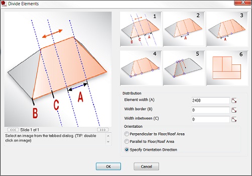
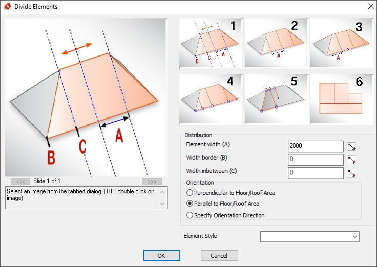
- Dynamic Divide - Will allow you to divide the floor plane into predefined equal widthsand if there is any remaining small panel you can freely place the remainingpanel where you wish. Or you can combine the small panel and a full panel andsplit it in half, this can then be placed anywhere if all panels are the samewidth you will only be allowed to split the first or last full panel in half.
Element width– Enter the width of your Element
Width Border– Enter the extra width of the side Elements, this value will be added to theElement width. Example: 5+100+1200
Width inbetween – Enter the width that you want between each Element, it will put halfon one side and the other half on the other side. Example: 5+1200+5.
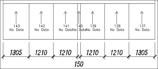
- Endpoint Divide - Will allow you to divide the element into predefined equal widths andselect a point which will become the endpoint of a panel and panels will thenbe created to the right and left of this point.
- Midpoint Divide - Will allow you to divide the element into predefined equal widths andselect a point which will become the midpoint of a panel and panels will becreated to the right and left of this point
- Divide Elements With Spacing – This method will allow you to enter thewidth of the element(A), enter a spacing between the elements(C) and also entera spacing on the element edges(B)
- Divide Elements Rotated With Spacing – This method is the same as the previousmethod but the elements are rotated horizontally.
- Left/Right Point Of Panel - Will allow you to pick the left and right side of each individualpanel, the panels can be of different widths if necessary. Note: This division utility does not require a plane at all. You are able to start from scratch.
Note: On many of these splitting options you will beprompted to specify span direction. Your cursor will be stuck to a corner ofthe plane and you’ll probably go horizontal or vertical. This is only to knowwhat direction to split the panels and the actual joist direction can bespecified latter on.
How to Add to Element

This command will add the area of a closed 2D polyline to a floor or roof element.The polyline will be projected on to the element (with UCS direction).
- Select hsbElements \ Add to Element
- Select the element(s) to be added to.
- Then select the 2D polyline to add to the hsbElement.
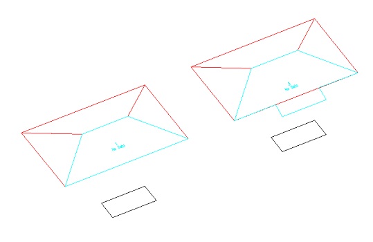
Note: When you are adding shapes to anelement, you should really do this one element at a time. The reason is thatshould you add the same shape to multiple elements, then you will end up withoverlapping elements.
How to Subtract from Element

This will subtract a polyline from an Element, you can subtract the area of a closed 2Dpolyline from an hsbElement. When you subtract a closed polyline from thehsbElement the polyline will be projected to the plane and a polyline shape cutout of the element (with UCS direction).
- Select hsbElements \ Subtract from Element
- Select the element(s) to be subtracted from.
- Then select the 2D polyline to subtract from the hsbElement.
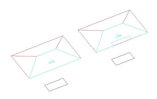
How to Split Edge

Split edge is used to split a side of an element in two or more sections. It allows you to put more roof or floor details at one side of an element.
- Select hsbElements \ Split Edge
- Select an element
- Select a point at a side of the element, to add the split on.
How to Split Element

Split Element is used to split an element in two. The best way to do this is, is toset the view on top view
- Draw a line at the points where you want to split the element.
- Select hsbElements \ Split Element
- Select the element that needs to be split.
- Select the split line
How to Join Elements
Join elements is used to join two elements.
- Select hsbElements \ Join Elements
- Select the two elements that you want to join.
How To Assign Roof Element Parameters

This command allows you to add theparameters to the roof elements. Without the parameters the elements won’tgenerate. By selecting this command the next screen will come up.
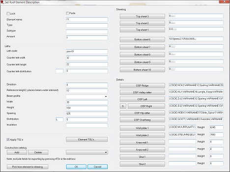
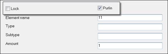
Lock - This preventthe element from generating.
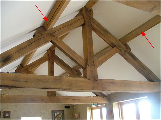
Purlin - Allows you to create purlin roof elements. The rafters are nowplaced horizontal.
(In architecture or structural engineering or building, a purlin (or purline)is a horizontal structural member in a roof.)
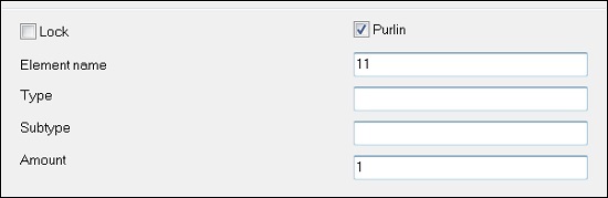
Element Name (Number) – This is the name thatis given to the element. If the element number is changed in the ‘set roofelement description’ screen, there is a chance that the program will not properlyhandle this change. It is better to change the element numbers with the‘renumber elements’ command (hsbGeneral\elements).
Type - This is an information filed that can be used in the database.
Subtype - This is an informationfield that can be used in the database.
Amount - This field will allow you to specify the number of times thiselement is required. However, please note that this is only a text entry thatwill be picked up in the BOM. If you work with the hsbDbase, it is better notto change it, but change the amount in the hsbDelivery.
Laths
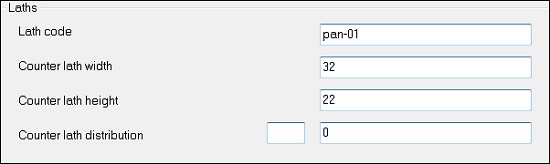
Lath code - This field is used to enter the code for the Laths as defined within the Distribution of tile lath command.
Counterlath width - This field is used to define the widthof the Counter Laths.
Counterlath height – This field is used to define theheight of the Counter Laths.
Counterlath direction – This field is used to define thedistribution of the Counter Laths. This is an option that can only be used whenyou create purlin elements.
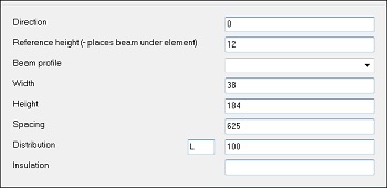
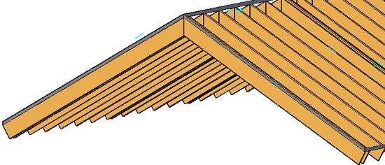
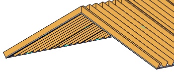
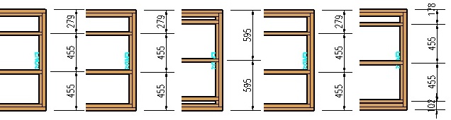
Reference height – This field is used to specify where thebeams/sheets are being generated in relation to the element outline. If you donot specify a value, then the element will be generated with the underside ofthe beams sitting above the element outline. By setting a "-" value,you can have the beams generated underneath the element outline.
ExampleReference height - 245
ExampleReference height 0
Beam Profile – Will give you thepossibility to use a predefined profile instead of a standard beam. Thiscontains a pick-list of all the extrusion profile that has been loaded withinthe extrusion manager. By selecting a profile, you are specifying that all thebeams in this element must generate using this profile.
Width – Joist width, Sets the value for thesize of the beams in the x or y direction, depending on the direction of thejoists. Or the x/y scale factor if using an extrusion profile.
Height – Joist height, Sets the value forthe size of the beams in the z direction Or the z scale factor if using anextrusion profile.
Spacing – Spacing between the rafters,Joist Spacing (Center Center)
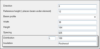
Distribution – This allows you to enterwhether the joists are to be distributed from the left, right or Center you canalso enter a number to give you the amount of beams in the element, you canalso specify an offset in the box on the right, reflected only in mm.
- Left – fill in an L in the field directly after ‘distribution.
- Right – fill in an R in the field directly after ‘distribution.
- Center – fill in an N (Normal Center) in the field directly after ‘distribution.
- A Number – Fill in a number and the amount youhave filled in will give you the amount of beams evenly divide from the centreof the Element
Example L Example R Example M Example N Example S
Insulation - Type the name of the material forinsulation. Text field outputted to BOM
Insert a TSL
Apply TSL’s – Select a specific TSL to attach to the floorelement.
Construction Catalog
Apply TSL’s – Select a specific TSL to attach to the floorelement. To add or to select previously added data whichyou can use in an element
Add - Is used for saving the values that arefilled out in the ‘Set Roof Element Description’ screen. The entry can be givena name and is saved as a default under the name that is given
Delete – Can be used to delete a default value. Byselecting a default value and selecting the ‘delete’ button, the default valueis disappeared. Pick from element in drawing.
Note: exclude fields for exporting by pressing F2in the edit box.

Pick from element in drawing – This allows you to pick the valuesfrom another element.
Sheeting
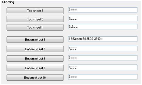
Top Sheet - Allows you to define sheeting in 'Set Sheeting Distribution' for zone 1 to 3
Bottom Sheet - Allows you to define sheeting in 'Set Sheeting Distribution' for zone 6 to 10
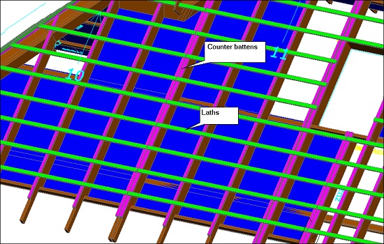
In hsbcad,ten sheeting zones are defined. Five zones for the top side of the element(zone 1 t/m 5) and five zones for the bottom side of the element. For the topside, two zones are predefined. Zone 4 is defined for the counter battens; zone 5 is defined for the laths. For the bottom side zone 10 is defined for insulation.
By pressing the button (top sheet or bottom sheet), the following screen comes up. In this screen you fill in the values that are needed to create sheeting.
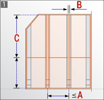
Sheeting distributions – Ten different sheeting distributions are defined.
Distribution 1
This distribution can be used to divide sheeting in roof and floor elements. In this division, the edge of the sheet will always be on a Rafter or beam. The sheeting width will be adjusted to meet the Rafters or beams. The sheeting will only get smaller than what is entered in the dialog box, never bigger.
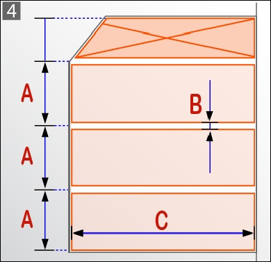
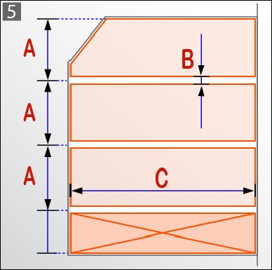
A: Enter the width of the sheet (add the gap value (B) to this entry)
B: Enter the gap.
C: Enter the height of the sheet.
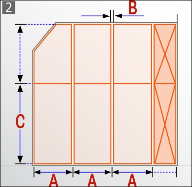
Distribution 2
This distribution can be used to divide sheeting in roof and floor elements. This division does not take the rafters or beams in account. If the sheeting is bigger than the Center Center of the rafters or beams it will place it next to the rafters or beams. The sheeting is divided from left to right and the rest will be placed on the right hand side.
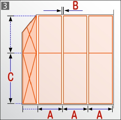
Distribution 3
This distribution can be used to divide sheeting in roof and floor elements. This division does not take the rafters or beams in account. If the sheeting is bigger than the Center Center of the rafters or beams it will place it next to the rafters or beams. The sheeting is divided from right to left and the rest will be placed on the left hand side.
Distribution 4
This distribution can be used to divide sheeting in roof and floor elements. In this division, the sheeting is placed transverse to the rafters or beams. The sheeting is divided from bottom to top and the rest will be placed on to top side.
Distribution 5
This distribution can be used to divide sheeting in roof and floor elements. In this division, the sheeting is placed transverse to the rafters or beams. The sheeting is divided from the top to the bottom and the rest will be placed on the bottom side.
Distribution 6
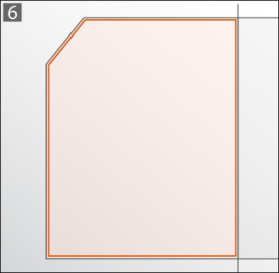
This distribution is intended for a full sheet, you only need to enter a thickness and material.
Distribution 7
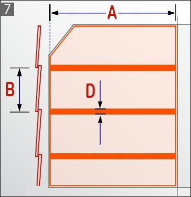
Distribution 8
With this distribution you can add an extra lath above and under the rafters or beams. The lath will run in the same direction as the rafters or beams. The center of the lath will be placed on the center of the rafters or beams.
A: Enter the width of the lath
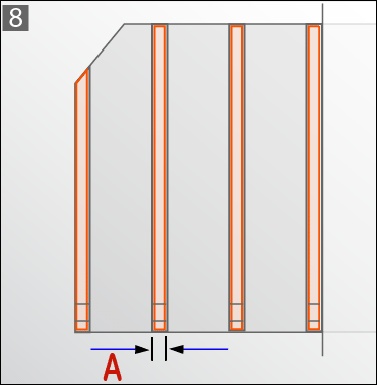
Distribution 9
With this distribution you can add extra laths above and under the rafters or beams. The laths will run transverse to the rafters or beams. The start point of the division is in the center of the element and the center of the rafters or beams.
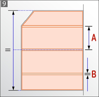
Distribution 10
With this distribution you can add extra laths above and under the rafters or beams. The laths will run transverse to the rafters or beams. The start point of the division is in the center of the element and in the center of 2 rafters or beams.
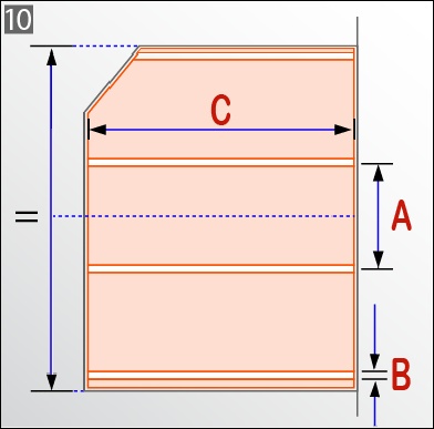
Details
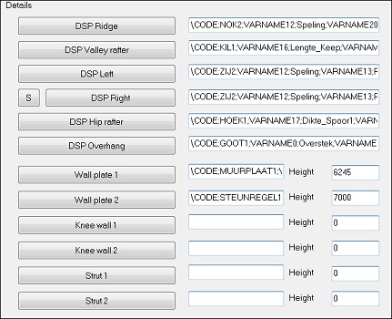
- Details – The details are used to create thedetailing of the roof element, these detail are flexible. By pressing a buttonon the left side of the screen, the values can be changed. The first sixdetails are made for generating the edge details of the element.
- DSP Ridge – Top side of the element.
- DSP Valley rafter – Bottom left or bottom right side ofthe element.
- DSP Left – Left side of the element.
- S – Switch the left and right side of the element.
- DSP Right – Right side of the element.
- DSP Hip rafter – Top left or top right side of theelement.
- Overhang – Bottom side of the element.
Theother six details are made for details that not belong to an edge; the extravalue that must be entered is the height of the system point of the detail.These details can only be created parallel to the ridge and overhang detail.
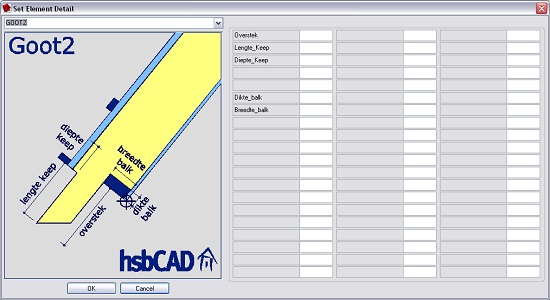
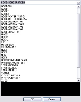
By pressing one of the buttons in the DSP details, thisscreen appears. At the top left side there is a list of DSP’s, that can beused. Below the list, a picture represents the detail that is used. At theright side the values can be added in the fields. There is a maximum of sixtydifferent values that can be added.
How to Assign Floor ElementParameters

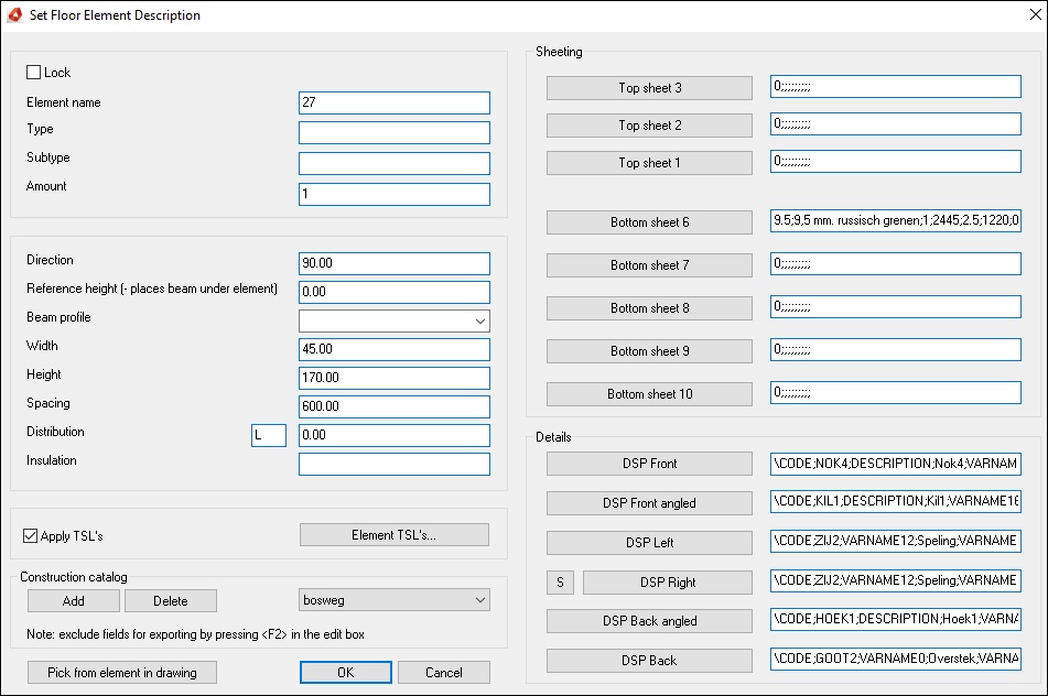
This command allows you to add the parameters to the floor elements. Without the parameters the elements won’t generate. By selecting this command the next screen will come up.
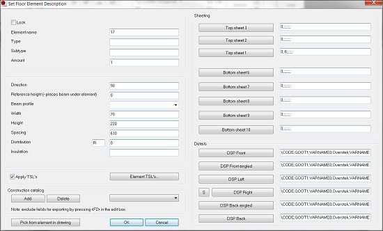
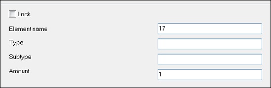
- Lock – this prevent the element from generating.
- ElementName (Number) – This is the name that is given to the element. If the element number ischanged in the ‘set roof element description’ screen, there is a chance thatthe program will not properly handle this change. It is better to change theelement numbers with the ‘renumber elements’ command (hsbGeneral\elements).
- Type – This is an information filed that can be usedin the database.
- Subtype - This is an information field that can be used in the database.
- Amount – The amount of elements that will be produced. If you work with the hsbDbase, it is better not to change it, but change the amount in the hsbDelivery.
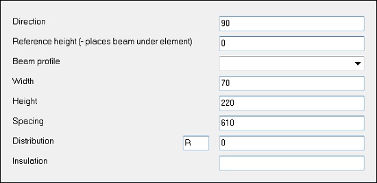
- Direction – Enter a value to direct yourfloor element, for example 90-180 degrees.
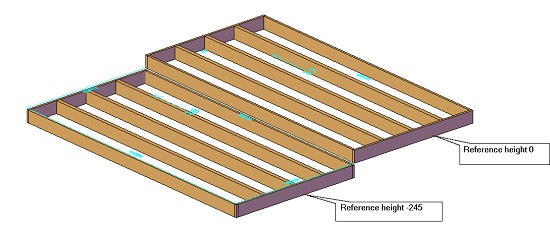
- Reference height – This field is used to specifywhere the beams/sheets are being generated in relation to the element outline.If you do not specify a value, then the element will be generated with theunderside of the beams sitting above the element outline. By setting a"-" value, you can have the beams generated underneath the elementoutline.
ExampleReference height – 245 and 0
- Beam Profile – Will give you thepossibility to use a predefined profile instead of a standard beam. Thiscontains a pick-list of all the extrusion profile that has been loaded withinthe extrusion manager. By selecting a profile, you are specifying that all thebeams in this element must generate using this profile.
- Width – Joist width, Sets the value forthe size of the beams in the x or y direction, depending on the direction ofthe joists. Or the x/y scale factor if using an extrusion profile.
- Height – Joist height, Sets the valuefor the size of the beams in the z direction Or the z scale factor if using anextrusion profile.
- Spacing – Spacing between the rafters, Joist Spacing (Center Center)
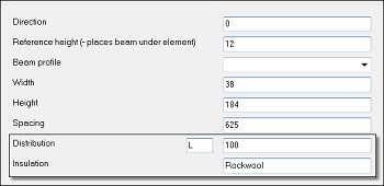
- Distribution – This allows you to enter whether the joists are to be distributed from the left, right or Center you can also enter a number to give you the amount of beams in the element, you can also specify an offset in the box on the right, reflected only in mm.
- Left – fill in an L in the field directly after ‘distribution.
- Right – fill in an R in the field directly after ‘distribution.
- Center – fill in an N (Normal Center) in the field directly after ‘distribution.
- A Number – Fill in a number and the amount youhave filled in will give you the amount of beams evenly divide from the centreof the Element
Example L Example R Example M Example N Example S
- Insulation - Type the name of the material for insulation. Text field outputted to BOM
Insert a TSL
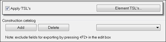
- Apply TSL’s – Select a specific TSL to attach tothe floor element.
Construction Catalog
To add or to select previously added data which you can use in anelement
- Add - Is used for saving the values that arefilled out in the ‘Set Roof Element Description’ screen. The entry can be givena name and is saved as a default under the name that is given
- Delete – Can be used to delete a default value. Byselecting a default value and selecting the ‘delete’ button, the default valueis disappeared. Pick from element in drawing.
- Note: exclude fields for exporting by pressing F2in the edit box.
- Pick from element in drawing – This allows you to pick the valuesfrom another element.
Sheeting
- Top Sheet - Allows you to define sheeting in 'Set Sheeting Distribution' for zone 1 to 3
- Bottom Sheet - Allows you to define sheeting in 'Set Sheeting Distribution' for zone 6 to 10
In hsbcad,ten sheeting zones are defined. Five zones for the top side of the element(zone 1 t/m 5) and five zones for the bottom side of the element. For the topside, two zones are predefined. Zone 4 is defined for the counter battens; zone5 is defined for the laths. For the bottom side zone 10 is defined forinsulation.
By pressing the button (top sheet or bottom sheet), the following screen comes up. In this screen can the values filled in that are needed to create sheeting.
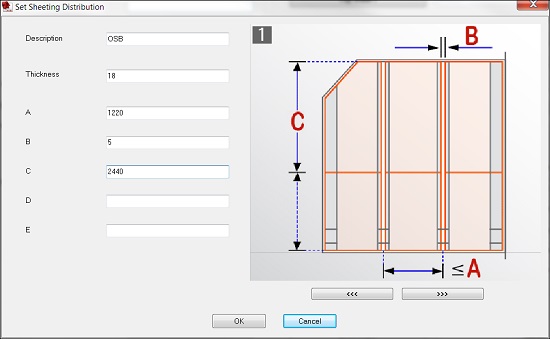
- Description – Description of the material thatis defined.
- Thickness – Thickness of the material
- A t/m E – values for the length, width of thematerials, Also gaps and / or overlaps can be defined. This depends of thechosen sheeting distribution.
Sheeting distributions – Ten different sheetingdistributions are defined.


- A t/m E – values for the length, width of thematerials, Also gaps and / or overlaps can be defined. This depends of thechosen sheeting distribution.
Details
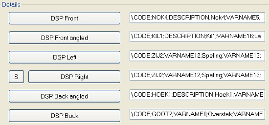
- Details – The details are used to create thedetailing of the floor element, these detail are flexible. By pressing a buttonon the left side of the screen, the values can be changed. The first sixdetails are made for generating the edge details of the element.
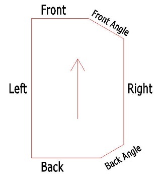
- DSP Front –The front of the element is the edge that the arrow points towards.
- DSP Front angled – The front angle will be any edge that is chamfered off of the frontside of the element.
- DSP Left –Will be the left hand edge as you look in the direction that the element’s arrow.
- DSP Right –Will be the right hand edge as you look in the direction that the element’s arrow.
- S – Switchthe left and right side of the element.
- DSP Back angled – The back angle will be any edge that is chamfered off of the back edgeof the element.
- DSP Back – Theback of the element is the edge that the arrow points away from.
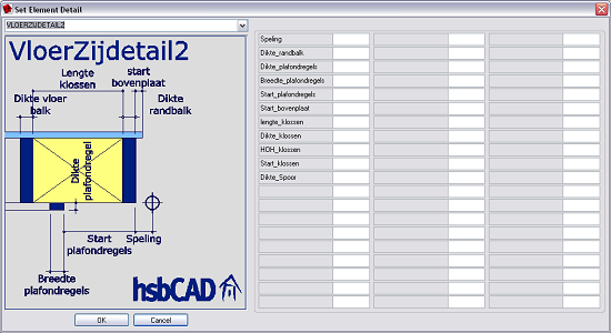
By pressing one of the buttons in the DSP details, thisscreen appears. At the top left side there is a list of DSP, that can be used.Below the list, a picture represents the detail that is used. At the right sidethe values can be added in the fields. There is a maximum of sixty differentvalues that can be added.
How to Assign Edge Detail

This command is used to assign a detail to an edge.
- Select hsbElement \ Assign Edge Detail.
Set beam to Element

This command is used to add loose beams to an Element.
- Select hsbElement \ Set Beam to Element.
- Select the element(s) to be added to.
- Thenselect the beam(s) that you want to add.
Support

This command is used to an extra DSP Detail; make sure you are on theright ‘Group’ Level.
Note: To insert support you must have a detailcreated for that.
- Select hsbElement \ Support.
- This will open the DSP dialog box.
- Select the desired DSP that you want to add to the Element. (for example Drukbalk DSP)
- Select the firstpoint and then the second point where you want the DSP to be placed.
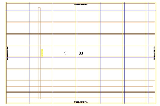
Create opening in Roof

This command is used to create an opening in a roof.
- Select hsbElement \ Create opening in Roof.
- This will open the ‘Set Element opening Descriptiondialog box.
- Fill in all information or select a pre definedselection.
- Place the opening in the Roof.
- Generatethe Roof element and an opening will be placed.
Create opening in Floor

This command is used to create an opening in a Floor.
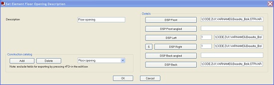
- Select hsbElement \ Create opening inFloor.
- This will open the ‘Set Element Floor openingDescription dialog box.
- Fill in all information or select a pre definedselection.
- Place the opening in the floor.
- Generatethe Floor element and an opening will be placed.
Sectionfrom Beside

This command is used to create a section of the roof or rather floorelement from beside.
This section is the base for the Distribution of tile lath
- Select hsbElement\ Section from beside.
- Select the biggest Element in your roof.
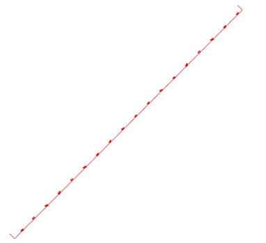
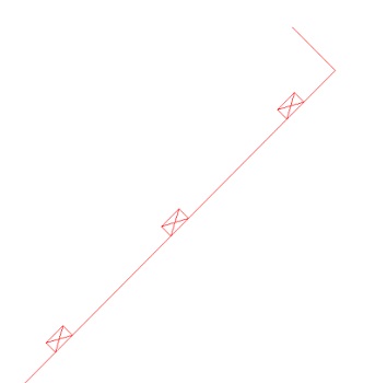
- A Red diagonal line will be created; select an insertion point (place it somewhere next to the Roof element)
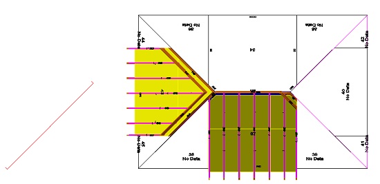
Distribution of tile lath

This command is used to add lath with a certain distribution to asection from beside.
In dialogbox Set Roof Element Description you can input the lath code.
- Select hsbElement\Distribution of tile lath.
- This will open the ‘Distribution of Tile lath’ dialogbox.
- Fill in the information or select a pre definedselection.
- Select the red diagonal line you just have made withthe command ‘Section from beside’.
- Select the bottom of this red line and then to top ofthe line (Upper).
- This will open another dialog box, enter a code.
- The laths will now be created on this diagonal line.(Fig1)
- You can now use this code in the Set Roof Element Description.
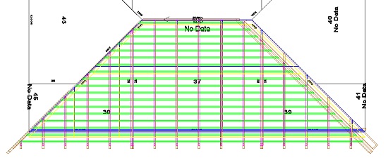
- TheLaths will automatically generate on the Roof element when you generate theElement. (Fig2)
Open DSP

This command is used to switch to a predefined profile (dsp10) ofAutoCAD. There you can define new element details.
The details are set for the edges in relationship to your elements arrow. The details are custom from office to office and are created by hsbcad technicians. Once youhave attached the data you are now able to generate your floors.
Note: If an element has no data you will get an error message. It is best toadd all your data before floor generation.
Sample Exercise
Draw Floor Outline
- Select hsbElement / Define Floor Panel Area, fill out the dialog box as below and select OK.
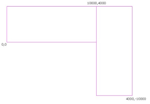
- Enter the points for the floor plane as below. When you have entered all the points press enter and your floor planes will be created at an elevation of 2600 and have a plane code of F.
Divide element by picking points
- Select hsbElement / Divide Element, select the first option box. Enter 2400 for the Panel Width (A).
- Select the Floor Plane on the left and indicate that the direction of the floor Span is at 90degrees. To position the panels, move your mouse until the dashed lines are in the same position as below. Pick with the left mouse button and your Floor Panels are created.
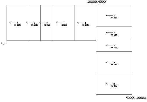
- Repeat the above process to create the floor panels from the floor plane on the right as shown above.
Assign Floor element parameters
Now thatyou have created the floor panels you can assign the details to the edges ofthe floor panels. Make sure that you have a directory containing floor detailsby selecting hsbGeneral/hsbSettings.The Detail Directories should contain an ElementRoof sub folder.
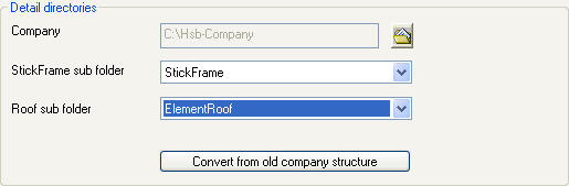
Floor Element Parameters
To assign the element parameters select hsbElement / AssignFloor Element Parameters and then select the Floor. On the Element Description Dialog complete the direction, size and spacing of joists as below.
Enter Floor joist Information
You willhave to fill in a minimum of the following
Directionof beams - 90
Width - 44
Height - 219
BeamSpacing - 400
Select the Details (Enter your ownvalues for timbers and spacings in each detail)
DSP Front - enter the detail (Vloerkopdetail)
DSP Left - enter the detail(Vloerkopdetail)
DSP Right - enter the detail (Vloerkopdetail)
DSP Back - enter the detail (Vloerkopdetail)
Add Sheets
Select thebutton for sheet 1and
Thickness -> 18
A -> 1250
B -> 0
C -> 2450
If you wantother sheets, repeat the process for buttons 2, 3, 6-10.
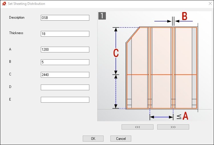
Assign the paremeters
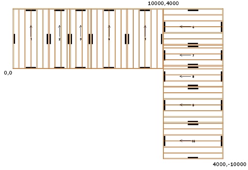
Now that you have selected the details to use, you can apply them to the panels. In this exercise you apply the details to the 5 vertical panels on the left. Select OK and pick the 5 panels when prompted.
Be aware ofthe arrow direction of the panels on the right.
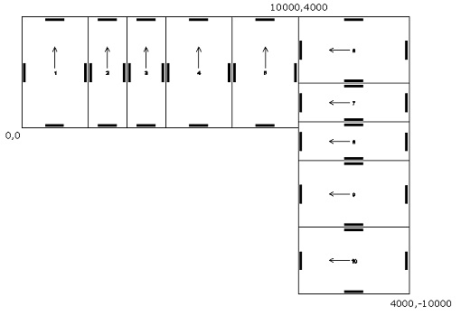
Change Details
The detail on panel 1 needs to be changed. You have several ways of changing the data
- Select hsbElement / Assign Floor Element Parameters and change the left detail by Copy Existing Element Settings. Change the settings for the left detail to (VloerZijdetail1), enter timbervalues and select OK and pick panel1 to apply the change.
OR
- Select panel 1, right click mouse, Edit element description and do the same as above.
Apply More details
Repeat theabove, to apply details to panels 6-10. This time set the direction of beams to180. Apply the same details that you applied to the first 5 panels. This timechange the right of panel 6 and the left of panel 10 to (VloerZijdetail1).
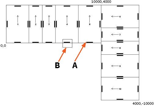
Subtract area from Element
To subtract an area from a panel, draw a closed 2D Polyline (rectangle) and use the command hsbElement / Subtract from Element.
- Select the Floor element (A), enter.
- Select the rectangle polyline (B) to be subtracted from the element.
Note: If the polyline is completely within the element panel, you will have to use the Create Openings in Element command instead.
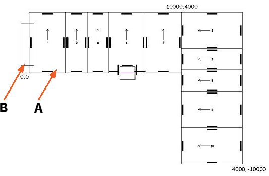
Add area to Element
To add an area to a panel, draw a closed 2D Polyline (rectangle) and use the command hsbElement / Add To Element.
- Select the Floor element (A), enter.
- Select the rectangle polyline (B) to be added to the panel.
Create Openings in Floor
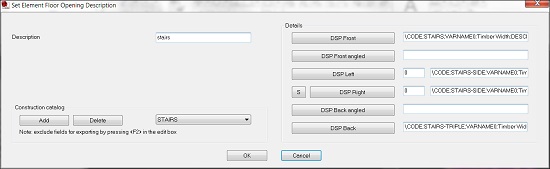
If you want to create a hole that is completely within a panel as in the next image, then you use hsbElement / Create Openings in Floor. Before you create the opening, fill out the details for the opening as below.
Description– Stairs
Front - Stairs_With_Double_Trimmer
Left - Stairs_With_Double_Trimmer
Right - Stairs_With_Single_Trimmer
Back - Stairs_With_Single_Trimmer
- Pick points for the rectangular opening similar to the opening below
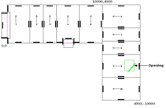
- Select hsbGeneral / Elements/Generate Construction to see how the construction will look like.
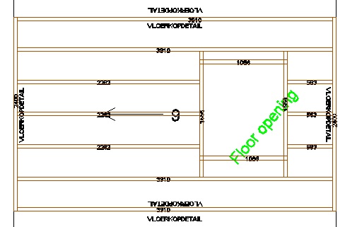
Modify Panel Parameters
Modify the panel on the left (Panel 1) by selecting the Element/right click/‘Edit element description in the flyout menu that appears. The ‘Set Floor Element Description’ dialog box will open. Change the direction to 90 instead of 180.
Renumber Panels
To renumber thefloor panels, select hsbGeneral/Elements/Re-NumberElements. On the Element Renumber dialog box select the settings as in the fig.belowSelect the floor panels in the order that you wish to renumber them. Note: the‘Allow cross window selection’ needs to be deselected. The numbers will beupdated on screen and also in the hsbConsole.
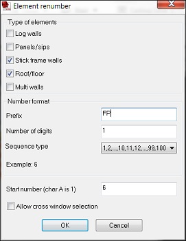
Prepare Panels For Manufacturing
Number Timbers
Before numbering the beams and sheeting you must generate construction.
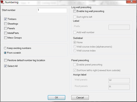
To number the timbers select hsbOutput / ApplyNumbering select timbers only. Select OK and select all the timbers of the floor panels.