
Sprung zum Abschnitt
Sie können die gesuchte Antwort nicht finden? Keine Sorge, wir sind hier, um zu helfen!
Kontakt zum SupportTSL | hsbWelding
Overview
This script generates 3D solid geometry and standardized 2D drafting symbols for welding seams between two entities (typically steel plates or connectors) within the timber construction model.
It visualizes the physical weld mass for clash detection and creates detailed ISO/EN symbols for shop drawings.
Usage Environment
Model Space --> Yes -->The script must be inserted and run in Model Space
Paper Space --> No --> Not supported directly in Layouts.
Shop Drawing --> No --> While the script runs in Model Space, it generates symbols that appear in generated shop drawings via MapRequests.
Prerequisites
- Required Entities: At least 2 Entities (Beams, Plates, or other constructive elements).
- Minimum Beam Count: 2.
- Required Settings: None required by default.
Usage Steps
Step 1: Launch Script
Command: TSLINSERT → Select hsbWelding.mcr from the list.
Step 2: Configure Initial Settings (Optional)
A dialog may appear allowing you to set initial parameters such as weld thickness or type. You can accept the defaults and change them later. Click OK to proceed.
Step 3: Select Main Part
Command Line: Select Entity 1:
Action: Click on the primary beam, plate, or component to be welded.
Step 4: Select Secondary Part
Command Line: Select Entity 2:
Action: Click on the secondary beam, plate, or component that joins the first.
Step 5: Define Weld Origin
Command Line: Pick point on welding edge:
Action: Click a point on the intersection edge where the weld should start.
Step 6: Define Weld Direction (X-Axis)
Command Line: Pick second point on welding edge (defines X-axis):
Action: Click a second point along the intersection edge to define the length and direction of the weld segment.
Step 7: Define Weld Plane (Y-Axis)
Command Line: Pick third point on welding plane (defines Y-axis):
Action: Click a point indicating the side of the joint where the weld bead is applied. This defines the "normal" direction of the weld.
Step 8: Finish
The script calculates the intersection and generates the 3D solid and/or 2D symbol based on the draw options.
Properties Panel Parameters
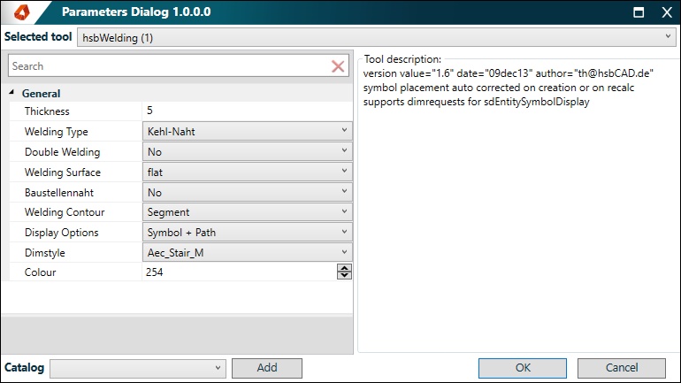
Thickness: 5 mm --> The throat thickness or leg length of the weld. Affects both the 3D volume and the size of the symbol.
Welding Type: Kehl-Naht (Fillet) --> The type of weld joint (e.g., Fillet, V, HV, Y, HY, I). Determines the shape of the 2D symbol.
Double Welding: No --> Specifies if the weld is applied on both sides of the joint.
Welding Surface: flat --> The surface finish contour (flat, concave, convex). Adds modifiers to the symbol.
Baustellennaht: No --> If set to "Yes", adds a "field weld" flag to the symbol leader line.
Welding Contour: Segment --> Defines the weld continuity: "Segment" (single line), "Ring" (closed loop), or "Contour" (complex shape).
Dipslay Options: Symbol + Path --> Controls visual output: choose to generate "Solid" (3D body), "Symbol" (2D annotation), "Path" (centerline), or combinations.
DimStyle: Current Standard --> The text style and arrow standard used for the weld symbol.
Colour: 254 -->The AutoCAD color index for the generated weld graphics.
Right-Click Menu Options
Menu Item Description
Swap Z-Axis Inverts the normal vector (Z-axis) of the weld, flipping the weld symbol to the opposite side of the joint.
Settings Files
- Filename: None
- Location: N/A
- Purpose: This script does not rely on external XML settings files.
Tips
- Automatic Updates: The script sets dependencies on the selected entities. If you move or modify the connected plates/beams, the weld geometry and symbol will update automatically.
- Path Restrictions: If you set Welding Contour to "Ring" or "Segment", the Double Welding option will automatically be disabled to prevent conflicting geometries.
- Visibility: Use the Draw Option property to toggle the 3D solid (useful for collision checking) independently from the 2D symbol (useful for clean drawings).
- Correction: If the weld symbol appears on the wrong side of the connection, use the "Swap Z-Axis" context menu option instead of re-inserting the script.
FAQ
- Q: Why did my weld disappear?
- A: Check if you modified the connected beams such that they no longer intersect or touch. The script requires a valid intersection between the two entities.
- Q: Can I show the 3D weld volume in drawings but hide the symbol?
- A: Yes. Change the Draw Option property to "Solid" or "Solid + Path". You can then use standard AutoCAD layer freezing to hide the solid in specific viewports if needed.
- Q: What does "Kehl-Naht" mean?
- A: It is the German term for "Fillet Weld," which is the standard triangular weld shape.